Powering Change
Installing since 2010 · 0118 951 4490 · info@spiritenergy.co.uk


- Commercial
- Residential
- by Technology
- Service Area
- Knowledge bank
- About Us
- Blogs & Case Studies

Power Factor is a measure of how much power is wasted by a lamp or electrical appliance.
Furthermore, electrical losses are related to the square of the current. If you need 25% more current, you have 1.56 times the losses.
As the Power Factor decreases even a small amount, the power company must generate more and more actual power in order for the appliance to operate. The more electrical devices with poor Power Factor, the more inefficient the power transmission system becomes.
For example a CFL (compact fluorescent lamp) has a Power Factor of less than 1.0, thus a 15W CFL might require the power company to produce 25W of actual power.
A homeowner will only be charged for the actual power used – 15W. But the power company still has to make that extra 10W so that the 15W CFL bulb can actually work properly with its 25W of “apparent power” – due to its lower Power Factor.
Hence you can believe you are ‘saving energy’ but you are not seeing the upstream losses and other issues caused by the use of the CFL bulb.
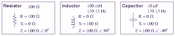
If you want to understand Power Factor in more depth you first need to know about Resistance, Reactance and Impedance:
Resistance is essentially friction against the motion of electrons. It is present in all conductors to some extent, most notably in resistors. When alternating current goes through a resistance, a voltage drop is produced that is in-phase with the current. Resistance is mathematically symbolised by the letter “R” and is measured in the unit of ohms (Ω).
Reactance is essentially inertia against the motion of electrons. It is present anywhere electric or magnetic fields are developed in proportion to applied voltage or current, respectively; but most notably in capacitors and inductors. When alternating current goes through a pure reactance, a voltage drop is produced that is 90º out of phase with the current. Reactance is mathematically symbolised by the letter “X” and is measured in the unit of ohms (Ω).
Impedance is an expression of all forms of opposition to electron flow, including both resistance and reactance. When alternating current goes through an impedance, a voltage drop is produced that is somewhere between 0º and 90º out of phase with the current. Impedance is mathematically symbolised by the letter “Z” and is measured in the unit of ohms (Ω).
In a circuit with a purely resistive load with no reactance (like an incandescent light bulb), the current is in phase with the voltage, and a plot of the voltage (e), current (i) and power (p) looks like this:
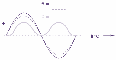
Note as the voltage and current are ‘in sync’ the power is always positive, and dissipated by the reactive load. It is not returned to the source, as it is with reactive loads.
With a reactive load, typically a motor (air conditioner, refrigerator etc), the plot of voltage (e), current (i) and power (p) looks like this:
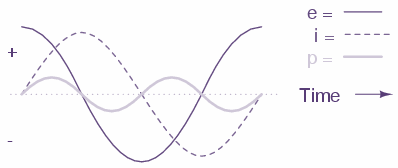
The power wave does become negative (equal negative to positive) and no circuit power is dissipated by the load(s). Rather, power is alternately absorbed from and returned to the AC source. Voltage and current are 90º out of phase with each other.
In a circuit combining resistance and reactance, the plot of voltage (e), current (i) and power (p) looks like this:
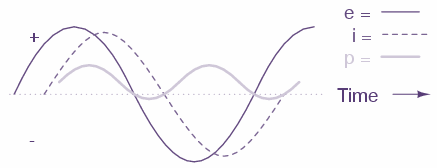
More power is dissipated by the load(s) than returned, but some power will definitely be dissipated and some will merely be absorbed and returned. Voltage and current in such a circuit will be out of phase by a value somewhere between 0º and 90º.
Power merely absorbed and returned in load due to its reactive properties is referred to as reactive power. Reactive power is symbolised by the letter Q and is measured in the unit of Volt-Amps-Reactive (VAR).
Reactive loads such as inductors and capacitors dissipate zero power, yet the fact that they drop voltage and draw current gives the deceptive impression that they actually do dissipate power. This “phantom power” is called reactive power, and it is measured in a unit called Volt-Amps-Reactive (VAR), rather than watts. The mathematical symbol for reactive power is the capital letter Q.
The actual amount of power being used, or dissipated, in a circuit is called true power, and it is measured in watts (symbolised by the capital letter P).
The combination of reactive power and true power is called apparent power, and it is the product of a circuit’s voltage and current, without reference to phase angle. Apparent power is measured in the unit of Volt-Amps (VA) and is symbolised by the capital letter S.
As a rule, true power is a function of a circuit’s dissipative elements, usually resistances (R). Reactive power is a function of a circuit’s reactance (X). Apparent power is a function of a circuit’s total impedance (Z).
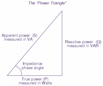
These three types of power are trigonometrically related to one another. In a right triangle, P = adjacent length, Q = opposite length, and S = hypotenuse length. The opposite angle is equal to the circuit’s impedance (Z) phase angle
There are several power equations relating the three types of power to resistance, reactance, and impedance (all using scalar quantities):
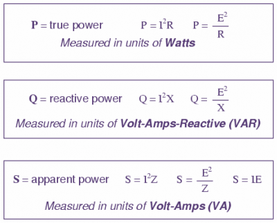
These three types of power — true, reactive, and apparent — relate to one another in trigonometric form. We call this the power triangle:
Find out more about LED lighting in our free guide: