
Powering Change
Installing since 2010 · 0118 951 4490 · info@spiritenergy.co.uk


- Commercial
- Residential
- by Technology
- Service Area
- Knowledge bank
- About Us
- Blogs & Case Studies

Victron Energy has been supplying off-grid and on-grid battery storage systems for use in automotive, marine, industrial and solar applications for over 50 years.
Victron manufactures inverters, battery chargers, inverter/chargers, batteries, battery monitoring systems and switchgear, and is known for technical innovation, reliability and build quality. Its products allow complete flexibility in design and are widely considered to be a reliable professional choice for the management of independent electric power.
Victron Energy is a Dutch company. However it offers full technical support in the UK.
Here are some of the reasons why we recommend Victron for certain projects:
Victron systems work well for grid-tied applications, using their ESS operation mode. An energy storage system (ESS) is used to store excess solar power in a battery for later usage on site, backup a property in the event of a power cut, and time-shift usage outside peak grid hours.
Victron has an additional (and optional) feature, unique to their design called BatteryLife, which optimises the operation of battery operation to preserve battery life.
Note that the Quattro allows the connection of both a generator and the grid - a feature which is not available with most battery storage systems, but which may turn out to be very useful if power shortages become part of our lives in the years to come.
For the Victron ESS with solar PV, you need:
Victron ESS systems can be configured for full or partial backup depending on requirements.
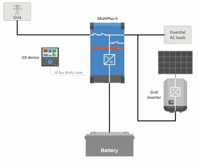
Full backup schematic:
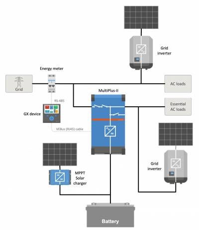
Partial backup schematic (with energy meter):
In the event of a power cut, the Victron inverter-charger can continue to power loads on its output. The changeover happens so fast (less than 20ms) that even sensitive electronic loads will continue to function without interruption. This is a key benefit of Victron systems compared with other systems (such as Tesla Powerwall) which can take a few seconds to changeover.
Our go-to batteries for Victron ESS systems are those manufactured by BYD. We typically use the 15.4kWh BYD Battery-Box Premium LVL. We also install Pylontech batteries. Their units are smaller, typically 2kWh to 3.5kWh; these are then 'stacked' to the required capacity.
Instead of connecting to the grid, a Victron system could be standalone (just solar PV, battery and Victron inverter-charger), or it could be connected to a generator, creating a standard 'off-grid' set-up.
Please note that we do not specify or supply generators; for this you need a local generator specialist who will be able to support you in maintenance and operation of the generator. That said, if you are interested in off-grid design, it is best to design the whole system before specifying the generator, for several reasons:
Key datasheets for Victron components:


